June 13, 2023
Getting ahead of PCBA failures early in the design phase
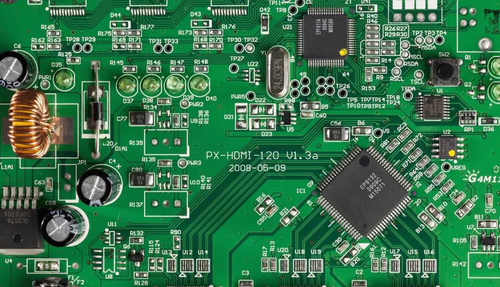
PCBAs are fundamental to almost every electronic device, from life-enabling smart phones to life-changing automotive integrations to life-sustaining medical devices. The quality and reliability of PCBAs are essential to meeting the demands of such diverse applications that not only perform critical functions but are expected to last for decades.
With advanced use cases, PCBAs have become increasingly complex and layered, meaning so too have their manufacturing processes. A single PCBA can contain tens of thousands of soldered joints, yet just one faulty solder joint can cause an entire board to fail. Even minor failures can impact a product's performance in the market, risking recalls, warranty issues, extensive design revisions, and more.
While functionality tests are important for demonstrating overall board performance, they may be insufficient to understand how PCBAs will wear with use or when exposed to environmental factors or how errors in process design, including surface mounting or wave-soldering, could result in product failures.
Build quality into your PCBA
To prevent PCBA defects, manufacturers can build and assess the quality of the PCBA early in the design phase to mitigate the many quality, reliability, and thermal issues that can affect performance.
Below, explore selected technical insights, including challenges, common failures, and best practices, from Exponent's work with PCBAs across industries.
Component-level considerations
A common vulnerability of PCBA components is excessive loads and failure due to insufficient consideration of structural and process designs. For instance, ceramic-based components (such as multilayer ceramic capacitors and thin-film ceramic resistors) are extremely fragile and vulnerable to unexpected assembly stresses originating from soldering and mechanical processes (i.e., PCBA panel separation or accessories installation). The specific packaging design of components (i.e., QFN device) may also have higher stress sensitivity levels than other designs. In addition, the tantalum capacitors may cause a thermal event or fire hazard if the PCBA is not designed to protect these critical safety-related components from structural stress.
Best practices for evolving industries
Soldering
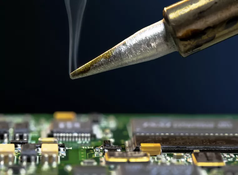
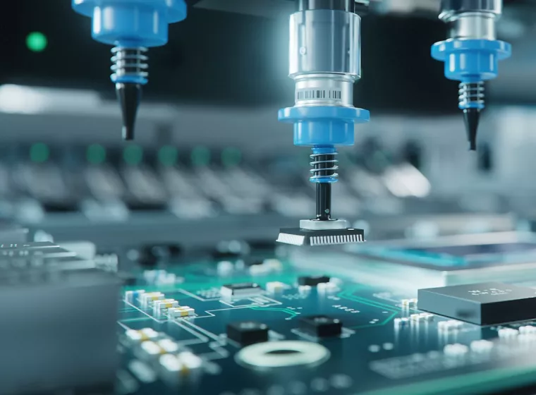
Electronics components are soldered onto PCB surfaces with solder alloy and flux to form solder joints. During PCB assembly, surface mounting and wave-soldering processes need to be performed with precisely controlled process parameters to mitigate possible product safety and reliability issues. There are several possible causes of soldering failures such as unbalanced thermal/mechanical design, improper solder reflow profiles, poor process control, mismatch of soldering properties between different components and materials, etc.
Failure Mode | Best Practices |
|---|---|
Cold soldering: Insufficient heating during soldering, or the heating is sufficient but because of excessive component deformation, the solder terminals cannot merge at the melting temperature of the solder alloy. | Design thermal relief or other process-related thermal features to enhance solderability or wettability. |
Head-in-pillow: A potential non-wetting problem occurs during the melting process of soldering, specifically for the BGA component reflow process. The solder ball from the BGA component is attached to the soldering pad with melted but unmerged solder paste. | Carefully select and design the process parameters to adapt the solder paste and flux categories. |
Bridging: The unexpected connection or contact of two solder joints that should not be electrically connected. | Conduct pre-warpage analysis when choosing large BGA components for the PCBA. Think about the warpage mitigation strategy during the initial design process. |
Excessive deformation of solder balls caused by warpage behavior differences between PCB and BGA components during the reflow process. | Evaluate a reasonable amount of solder paste stencil printing. |
Hot-tearing: The bulk solder separated from the intermetallic compound during or just after reflow due to excessive cooling deformation or gradient of cooling rate in solder joints. | Design thermal balance and mechanical balance features properly for the PCB |
Non-wetting: The solder, soldering pad, or terminals failed to soak by flux or molten solder under the reflow process and cannot form any effective soldering connection. | Implement strict quality controls during the row material incoming process to prevent excessive oxidation or improper storage temperatures. |
Component process damage. | Perform manual or automatic quality inspections before and after the process. |
Thermal impact
Electronics have become faster, smaller, and more functionally complex, requiring more power and raising operating temperatures. With over half of all electronic components now failing due to heat stress/coefficient of thermal expansion (CTE) mismatch or thermal-induced material degradation, it's critical to design your PCB with efficient thermal performance.
Design Concerns | Best Practices |
|---|---|
High-power/heat-generating components. | Maintain adequate component spacing between high-power components; strategically locate components according to their heating power. |
Thermal-induced excessive warpage of PCB and component. | Design thermal vias or use a thicker copper foil in the PCB layer stacking to enhance thermal dissipation. |
Thermal stresses and repeated stresses causing overload and fatigue of solder joints and components. | Use PCB lamination with a lower CTE mismatch with the component. |
Overheating causing material/component damage or long-term degradation. | Perform computational simulations on the thermal warpage behavior of a PCBA before the design is finalized. |
Non-uniformed heating effects of PCBA causing distortion. | Add external thermal dissipation features such as heat sink or fans. |
Additional best practices to improve thermal performance include enhancing the mechanical or structural connections in large thermal deformation regions, designing overheating protection features in the circuit, uniformly distributing the high-power components, adding thermal balance features on the PCB, placing high-power components in more rigid areas, and designing a reasonable backplate mounting structure to prevent the distortion of the PCBA.
Explore more about identifying and solving PCBA quality issues early in the design process.
What Can We Help You Solve?
Exponent has extensive experience helping clients review their design and manufacturing processes to improve product quality and reliability. Our multidisciplinary teams evaluate the degradation of PCBA materials, assess their effects on the product lifecycle, identify potential defects and quality issues, and provide solutions and mitigation methods.
Discrete Components & Printed Circuit Boards
Optimize the reliability of your discreet components and printed circuit boards.
Electrical Materials & Circuit Packaging
Overcome challenges in electrical materials and packaging, such as semiconductor and dielectric materials.

Electrical Devices & Consumer Products
Product design validation, risk assessment, product launch support, failure analysis, product recalls, and more.
Hardware Logic Design & Analysis
Expert insights for the design, analysis, and functional verification of integrated circuits and systems.

Factory Audits & Materials
Improve process performance and product quality with expert factory audits and materials evaluations.
Insights

