November 1, 2024
How simulations and real-world data can help make carbon dioxide injection well tubing safe and functional for decades to come
Carbon capture and sequestration (CCS) projects are on the rise around the globe, thanks in part to government funding in Canada, Europe, the UK, and other parts of the world. In the U.S., the Bipartisan Infrastructure Law has earmarked more than $2.5 billion, with industries ranging from major steelmakers to technology companies pursuing CCS projects to offset emissions from industrial operations, whether from iron ore processing or energy use for data centers. Around the world, according to the Global Carbon Capture Institute, the number of CCS projects rose by approximately 57% between 2022 and 2023 (from 199 to 312), with more being added each month.
Carbon capture facilities harvest carbon dioxide from industrial processes, compress it, and then inject that compressed carbon dioxide deep into geological formations through vast underground wells. The injection process must use high pressures (typically above 1,200 psi) to push the compressed or liquefied carbon dioxide deep into the earth (typically at depths of 800 m/2,725 ft), below the level of drinking water aquifers.
The steel tubes that carry carbon dioxide into wells are critical components that must last for years without leaking. Even small fractures in tubing can release tons of carbon dioxide into the environment, negating the energy and effort spent to capture and store it. Operators have relied on extensive experience with oil and gas wells and extensive analysis of failures over decades to determine its durability.
Today, with the benefit of real-world data from operating CCS projects around the world, site operators and owners have far more advanced tools to assess risks to injection well tubing. Critically, when this data is combined with advanced computer simulations that model the durability and longevity of tubing against both specific and compound operational and environmental conditions at a given location, it can result in proactive, optimized strategies that help identify risks and prevent failures.
Real-world injection well tubing data
The longest-running CCS site in the U.S. was founded in 1972. The Terrell Natural Gas Processing plant in Texas captures carbon dioxide during gas processing and transports it via the Val Verde pipeline, where it's injected into the Sharon Ridge oil field and other areas for enhanced oil recovery. In this case, compressed carbon is used to push hard-to-recover crude oil out of deep wells and up to the surface to be processed. Several other sites across the nation use compressed carbon in a similar manner, like the Enid Fertilizer plant started in 1982 and the Shute Creek Gas Processing Facility started in 1986. Knowledge of the factors that affect the durability of injection well tubing at sites like these has been developed over decades, contributing to understanding of how critical vulnerabilities develop.
When any fluid flows through a pipe, the pipe vibrates in response. These vibrations result in small, repetitive deformations in the pipe material (i.e., cyclic stresses) which, over time, can lead to the formation and growth of fatigue cracks. Vibration can also cause injection well tubing to rub against surrounding materials (such as pipe casings or cement). Over time, friction against these materials can cause wear and, eventually, cracking and leakage. Primary causes of injection well tubing failure include the following.
- Vibration and Fatigue: High flow rates or large pressure differentials can induce vibrations in the well tubing, leading to failure from fatigue over the long term. This is a non-trivial concern for wells designed to operate for 50 years or more.
- Wear/Erosion: The flow of fluids, especially those containing solid particulates, can cause wear/erosion of the well tubing. This erosion can thin/weaken the tubing and contribute to failures.
- Corrosion: The materials used in well construction can corrode over time, resulting in potential metal loss and, consequently, compromising the structural integrity of the well.
To help ensure safety, well tubing is engineered according to British Standard BS 7608 (Guide to fatigue design and assessment of steel products) and the Energy Institute Guidelines for the Avoidance of Vibration Induced Fatigue Failure. However, these standards are not specific to well tubing or the complex factors that have the potential to impact its integrity deep underground.
Numerical simulation of injection well tubing
The primary challenge in assessing the durability and lifespan of injection well tubing is predicting its long‑term integrity. High flow rates of carbon dioxide can induce vibrations that may lead to fatigue failure. Carbon dioxide in the presence of moisture can also cause corrosion in carbon steel pipes over time. Mechanical models and simulations are often used to evaluate the long-term performance of injection well tubing, including mechanical stresses, thermal expansion and contraction, geological factors such as erosion, and additional corrosion factors.
Numerical models of injection well tubing offer owners and operators critical insights for evaluating the lifespan of their proposed well tubing and mitigating potential failures. Here are some of the key factors that inform these simulations, along with steps operators can take to address potential problems.
- Fluid flow excitation caused by turbulent flow and acoustic resonance, the associated vibration levels, and their impact on the tubing: Vibrations caused by flow excitation can cause fatigue in tubing and tubing joints, a problem that can be exacerbated by multi-phase flow. If simulations predict that excitations will lead to tubing failure over time, operators can choose to reduce flow rates or increase the diameter or stiffness of their tubing to enhance durability and longevity.
- Stress response of the tubing under pressure variations mapped using finite element analysis (FEA): This can reveal critical insights into potential failure points. Based on the information gleaned from FEA, operators may choose to optimize their design parameters such as increasing the tubing diameter or stiffness.
- Material integrity or the corrosion and erosion properties of the material being used to assess the selected steel tubing's ability to withstand predicted stresses and degradation rates over the project's lifespan: Again, operators may choose different tubing materials or use corrosion-resistant coatings to reduce corrosion and erosion over time.
Using these computer numerical models, CCS project operators can gain insights into how their injection well tubing will perform over time and make adjustments that could optimize tubing selection to match injection rates, extend its lifespan, help prevent damage to the environment, and reduce costs and downtime in the event of a failure.
The future of injection wells
With more carbon storage facilities being built, assessing the durability and longevity of injection well tubing will become more important. Existing pipeline and engineering standards will be helpful in developing these CCS projects, but new standards are likely to be developed specifically for injection wells. In the meantime, and in many unique cases, using computational modeling combined with real-world experience is crucial for predicting injection well tubing durability and longevity. If carbon capture is going to play a role in decarbonization and climate mitigation, advanced modeling will be critical to designing long-lasting CCS projects.
What Can We Help You Solve?
Exponent's multidisciplinary oil and gas industry experts — including metallurgists, materials, corrosion, mechanical, and thermal specialists — partner with pipeline operators to understand integrity management assessment methods, limitations, input data, and the overall process for optimizing asset safety.
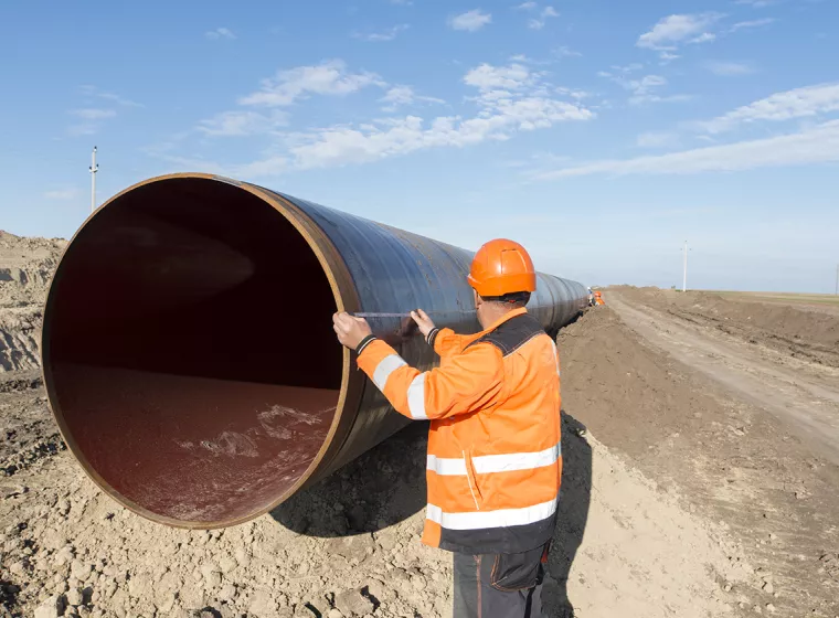
Materials & Corrosion Expertise for Pipelines and Process Piping
Minimize pipeline and piping failures with integrity and pipeline risk assessments.
Oil & Gas Pipelines
Multidisciplinary support for oil and gas pipeline challenges at every point in your asset lifecycle.
Pipeline & Process Piping
Mechanical engineering expertise for pipeline construction, pipe corrosion, pipeline integrity management, and pipeline failure analysis.
Gas Pipeline Blowdown Risk Assessment
Manage pipeline blowdown hazards with modeling, risk assessment, and process safety advising.
Materials & Corrosion Expertise for Utilities
Real-world risk and degradation models to help prioritize infrastructure improvements and operational decisions.
![Liquefied Natural Gas (LNG) [TS]](/sites/default/files/styles/cards_home_card/public/media/images/GettyImages-854095408.jpg.webp?itok=hoWL7ZTm)
Liquefied Natural Gas
Consulting services for the safe handling, transportation, and storage of liquefied natural gas (LNG).
